
I don't normally write up most of the Commodore PET repairs I do, because they generally follow the same patterns of RAM faults, ROM faults, and occasionally a bad CRTC. Sometimes all three.

As you might have guessed, this is not one of those.
I think I need a disclaimer.
These posts are not troubleshooting guides. They are documentation of the process I went through to fix a specific fault. They are unlikely to help in your case unless your fault has the exact same cause (not the exact same symptoms). If your PET is dead, it is most likely a ROM or RAM fault (or both). Get yourself a PET ROM/RAM board that will probably fix it. If it is a later 4032 or 8032, maybe the 6545 CRTC will also be bad, but still likely a ROM or RAM fault.
This board shows all the hallmarks of a dead 8032, no video output, no chirp. On these machines, video is generated by a 6545 CRTC chip. This needs to be initialised correctly to generate video output. If the CPU does not get to the stage of running the setup code, then you don't get a video output. Sometimes you do get a chirp, this usually means the CPU has got that far, but the CRTC chip is not working, or something is stopping it from hearing the setup commands.

Here it looks like this board has already been through the 6545 failure as the 6545 has been replaced by a 6845. That is functionally compatible, and I think has some extra features that the 6545 doesn't.
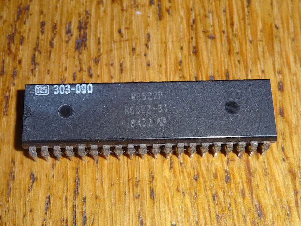
Looks like the 6522 has also been replaced, in this case with an RS part number painted on the top. They are probably out of stock of those now.
To get around the video issue, I removed the five 40 pin chips and fitted a known good 6545 and a PET diagnostics module. That will do the setup of the video chip and should generate a display.

OK, sort of progress, there is no a display, but not a good one.
Note 1 - It may look like it, but this is not a vertical sync failure, it's presumably misheard the instructions and set a very short page size.
Note 2 - I am incapable of taking decent pictures of the PET CRT. Get used to it. It's not going to get any better.
Checking the databus, you can see why it might get confused, rather than nice clean one and zeros of 5V and 0V, this is a mismash of fractions, with bits of signals at 1 and 2 volts.
I would like to have included a scope trace at this point, but I don't like running machines too long with active bus conflicts, so I didn't get any pictures that were good enough.
This is indicative of bus conflicts, and usually means several things are writing to the bus at the same time. This seems to happen a lot of the 6540-xx ROM chips and 6550 RAM chips used in the original PET, but less so with the later mask ROMs used on these machines.
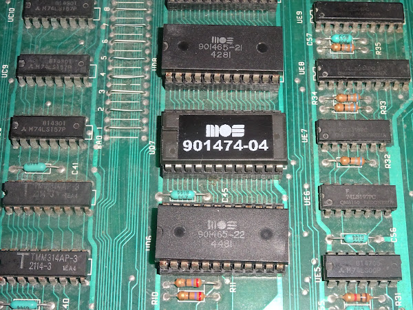
The ROMs are all socketed, so time to remove them, in case it is one of those to blame.

That is better, now there is a full screen, but it's a full screen of rubbish.

Time to do some poking around with the scope.
The address lines are all wiggling around as they should be, in all the appropriate places. Due to the amount of chips on the PET board, these are buffered in a few places due to the limited number of chips the buffer chips of that era could drive. Fan out is barely an issue these days with HC logic chips that can drive a seemingly unlimited number of chips.

Pin 20 on all the ROM chips was doing odd things. These are the enable lines, and should all be high apart from the one currently selected.
But they are not.
All of those are generated by the 74154 4-16 line decoder chip. This takes the top 4 address lines and generates 16 enables signals, one for each 4K block in memory. These are active low, so should normally be high with just one of them low, indicating the block currently selected.
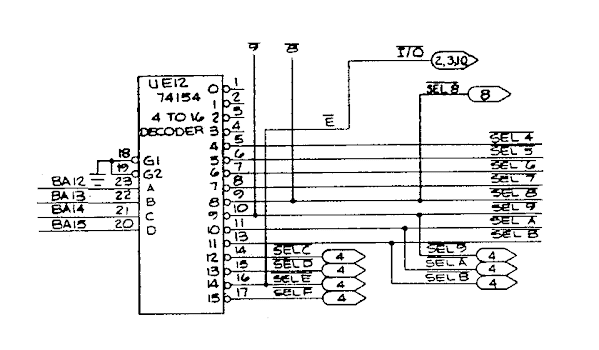
Probing that directly, it's clear that some are high as they should be, but several are low, and a few are floating. Hmm, that's not good.

The chip fitted is actually a Mitsubishi M53354P, but I guess that's a compatible part.
That looks a bit crusty, as do several of the chips around it. It is near what would have been a slot in the case, so is where moisture could most easily attack the board.

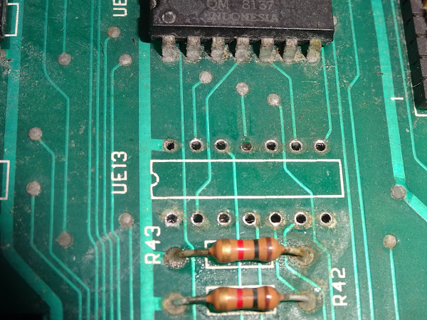
Even after a bit of a clean up, the legs of the 74LS10 look the worst hit, so time to remove that and the 74154 (or whatever that Mitsubishi part number was).

The traces around the 74154 look intact, but one of the traces to the 74LS10 was corroded through, so will need to be repaired (pin 11, middle top).
The 74154 equivalent failed the test, so that was indeed the main culprit.
The 74LS10 was probably OK, but the pins were too corroded to test it properly.

The 74154 is now out of production, and I am down to the last few from the last full tube I bought many years ago when they were still available.

I patched the corroded trace to the new 74LS10, which went neatly to a via above, and checked the continuity of the others.

With that replaced, I got a display.

Miraculously, the RAM all passed.
It is showing a few faults in the video RAM, but nothing visible on the screen. The timing is extremely tight on the video RAM, so much so they alternate odd and even pixels between two chips at a time as a single one wouldn't be fast enough.
The main RAM looks awful, so probably best to leave that alone if it's working.

Some people suggest washing boards like this in a dish washer. Not a fan of that idea, I am thinking about water getting trapped under chips, potential delamination of ceramic packages like those. And also, that board is pretty grotty, no way am I putting that in my dishwasher.
I started putting the chips back in, testing after each one, and it continued to work.

The only problem was one of the ROM chips.

It is showing up as empty. I checked the power pins and the enable line, and they were working correctly, so I guess the chip was just faulty.

This is the only 2K ROM chip, the others are 4K, so it can be replaced by a standard 2716, or in this case, a 2816. The others need non-standard 2532 EPROMs or adapters.

The label turned out quite nicely, maybe a bit large, but I'm OK with that.
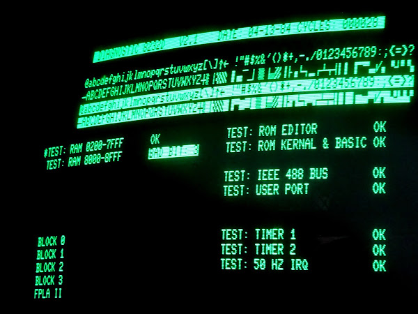
With that replaced, it passed the tests. (note, the screen shows a later run of the test with a different ROM chip, one I made with a modified keyboard table so I could use the normal keyboard on the 4032 I was testing this in, rather than the business keyboard it was expecting.)

OK, nothing left for it, time to put the 6502 back and see if it will live again.

Yay, success, we have a ready prompt.
I did a bit more testing, and all seemed fine, the IEEE-488 bus was working, after I cleaned the edge connectors, so I was able to load further games and test programs from an SD2PET.

I left it running the 8296 diagnostics program.
That again picked up the odd fault with the video RAM, but it doesn't seem to affect the screen in normal operation, so as I said before, I will leave that alone. There may be a fault somewhere in the second or third column full of chips here, but the 8032 seem to be very picky about 2114 RAM chips, so it is quite difficult to find replacements that will work.

Advertisements
PET ROM/RAM
As mentioned above, many PET faults are down do bad ROM chips or bad RAM chips, and a PET ROM/RAM chip can often help bypass those. You can order one from The Future Was 8 bit.
https://www.tfw8b.com/product/commodore-pet-rom-ram/
More info in a previous post:
http://blog.tynemouthsoftware.co.uk/2022/08/testing-pet-rom-ram-boards.html

Mini PET B
Or if you want an easier solution, the Mini PET B is a drop in replacement for a PET / CBM 40 column 32K motherboard.
More info in a previous post:
http://blog.tynemouthsoftware.co.uk/2023/10/building-a-mini-pet-b-kit.html
Mini PET B at SellMyRetro:
- Built and tested - https://www.sellmyretro.com/offer/details/63875
- Full Kit - https://www.sellmyretro.com/offer/details/63876

PET IEEE-488 Diagnostics
The PET IEEE-488 Diagnostics module is available from my SellMyRetro store, in assembled or kit form.
More info in a previous post:
http://blog.tynemouthsoftware.co.uk/2023/10/pet-ieee-488-diagnostics-updated-version.html
PET IEEE-488 Diagnostics module at SellMyRetro:
- Built and tested - https://www.sellmyretro.com/offer/details/63989
- Full Kit - https://www.sellmyretro.com/offer/details/63987

PET Diagnostics.
The PET Diagnostics modules are available from my SellMyRetro store:

Patreon
You can support me via Patreon, and get access to advance previews of posts like this and behind the scenes updates. These are often in more detail than I can fit in here, and some of these posts contain bits from several Patreon posts. This also includes access to my Patreon only Discord server for even more regular updates.
https://www.patreon.com/tynemouthsoftware
