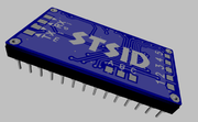
Sent to Oshpark (in USA) so now wait a week, first class mail from Oregon to Florida is super fast, normally takes 2days, so I should have it in 8-10 days.
Stats:
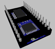
MCU 16Mhz STM8S003K3T
8K flash, 1K ram, 128bytes eeprom.
This 8bit mcu have many of the features of 16/32bit mcu.
20bit address space so no page flipping 256byte blocks.
32bit opcode, but similar to 6502 simplicity so I think writing software in
assembler for speed and time determinized.
PWM audio:
Though 16bit is possible, even at 16MHz a period would be 256Hz lol
10bit would be 16KHz period, reasonable but rms hum or freq cut-off in the r/c filter.
8bit a very good 65KHz period, but resolution is... 8bit
So 9bit:
Doubles the resolution but use a gpio as highbit to the resistor adder,
and 8bit pmw for the lower bits.
Or could do 6bit pwm + 6bit pwm as highbit gpio can also be on the same timer as compare2.
This timer only have 3 compares, so stereo would only be 9bit on one of the channels.
This mcu have another timer with 4 channels, but due to pin layout trying to be so data and address lines up on ports in a continues order, I did not try this at this reversion.