
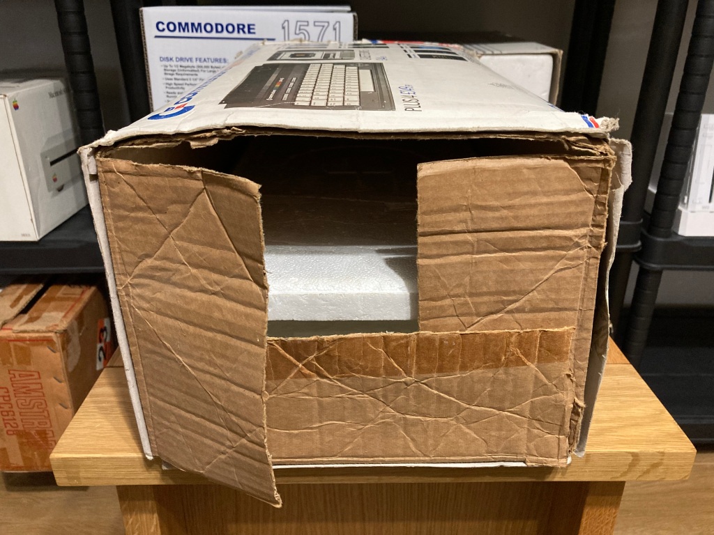
A while back I got my hands on my first Commodore Plus/4, yet another 1980s 8-bit computer to add to my collection. The machine was in good condition and came with several accessories and its original box, however it was sold as “untested”.
The Commodore Plus/4 was one of the Commodore 264 line of 8-bit home computers, which were designed to be a low-cost equivalent to the C64 and C128. The Plus/4 was the “premium” offering, marketed at business professionals – it had 64KB RAM, built-in productivity software, a serial port, a black wedge case, and a mechanical keyboard.
The 264 series was not a commercial success, though the C16 and Plus/4 had reasonable sales in Europe, so the Plus/4 is relatively easy to find.


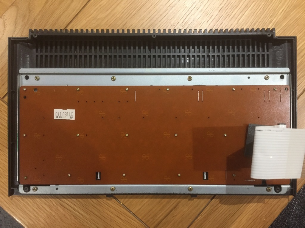
The Plus/4 seemed to be all original, and featured a 1984 310163 REV.D mainboard with 64 KB of factory-installed RAM – the CPU, ROMs, PLA, and TED were socketed.

After checking that the PSU was working OK, I did a quick power-on test – the computer seemed to output video, but only displayed a “garbage” screen with flashing blocks and lines, and various artefacts which changed on reset. The unit required repair.


In the Plus/4, a garbage screen fault is a common failure mode which can indicate all kinds of problems: typically, a video subsystem problem, an addressing problem, or a RAM problem, all of which can be caused by a power issue or a failed IC. Most of the ICs on the board are connected to the data or address bus, so there are a large number of potential problems that need to be worked through.
The first thing to check with any repair is that power is being correctly received on the board, which may indicate a problem with the power socket, power switch, or fuse – I checked for 9Vac and 5Vdc at the user port, and both were OK.
A constant reset can also cause a garbage screen – I checked the reset signal at the user port and it worked as expected, staying low (around 0Vdc) for about a second at power on, then going high (around 5Vdc). Pressing the reset button made no difference.
I checked for signs of previous rework which could indicate a potential problem (flux residue, non-factory sockets, etc), but there was none; I also checked for physical damage on the board which could be causing connection problems, including scratches or cold solder joints, but the board was pristine.
I reseated all of the socketed ICs and cleaned all sockets, ports, and switches with contact cleaner, however there was still no change in symptoms.
At this point I decided to aim my investigation at the ICs themselves, starting with the socketed ones as these are easy to remove and test.
I started with the MOS 7501/8501 CPU, which is proprietary to the 264 series of computers – this is notoriously unreliable due to it being manufactured using the new and unproven (at the time) HMOS process. I tested this in my 264-series test board alongside a set of known-good ICs and it seemed to be OK.
I repeated this for all of the other socketed ICs (TED, PLA, Kernal ROM, BASIC ROM, function HI ROM, function LO ROM), and these all seemed OK too.
This meant that it was a problem with a soldered IC (or ICs) or the board itself.
I pulled out my IR thermometer to measure the temperature of all of the ICs, to check for any outliers. IC failures often lead to gates shorting or pulling on inputs or outputs, which draws more current, which increases die and package temperature – this can range from a subtle difference to something that could quickly burn your finger (i.e. RAM ICs damaged by overvoltage). In this case, I didn’t find any outliers.
I decided to remove and replace the two multiplexer ICs (U9 and U10), which are involved in RAM addressing and can cause these kind of symptoms – on this board these were MOS Technology 8708 ICs, equivalents to the 74LS257 which are known to be less reliable than the other brands of the time (i.e. Texas Instruments).

I desoldered these ICs using my desoldering station (a Duratool D00672), taking care not to damage the board. Then, I installed a set of new-old-stock 74LS257 ICs, available from Retroleum – I didn’t install any sockets as I wanted to keep the board looking stock. Unfortunately, this didn’t change any of the symptoms.
After this brute-force approach, I decided to invest in a diagnostic cartridge and loop-back harness (similar to those linked), to add to my test equipment. With the diagnostic cartridge installed, which can identify potential boot problems (such as bad RAM), the screen flashed eight times, indicating a problem with the 4164 DRAM IC at U18.
I removed U18 and replaced it with a new-old-stock 4164 DRAM IC, available from Retroleum – again, I didn’t install any sockets as I wanted to keep the board looking stock. I tested the original 4164 RAM IC from U18 using my RAM tester, and it was indeed bad. With a new RAM chip installed, the computer now seemed to boot correctly (with flashing cursor and correct amount of RAM showing). It also passed all diagnostic tests with a diagnostic cartridge and loopback harness installed.

I also replaced the working MOS 8501 CPU with a modern-made CPLD-based equivalent, which is much more reliable than the original IC. It is also possible to get kits which replace the CPU with the more readily available MOS 6510 from the Commodore 64, but these require a modified Kernal ROM to function.

Now that the machine was working again, I wanted to perform some preventative maintenance, starting with the electrolytic capacitors – these are commonly used for filtering, smoothing, and decoupling in both high- and low-voltage electronics.
Electrolytic capacitors typically comprise aluminium windings insulated by a liquid electrolyte, which can dry out over time and negatively affect performance (even failing dead short), or leak out and cause corrosion to the PCB and surrounding components.
As such, I always replace all the original electrolytic capacitors with high-quality modern equivalents – this doesn’t take too long on the Plus/4, as there aren’t many.
I usually remove all of the capacitors at once using my desoldering station (a Duratool D00672), then install the new ones one-by-one whilst taking particular care to ensure that the value, voltage rating, and orientation are correct – electrolytic capacitors are polarised, so must be installed the correct way around, else they’ll blow up during use.
You can’t always trust the markings on the PCB silkscreen, as sometimes mistakes were made in the design from the factory (take the Commodore CD32, for example), so care must be taken to match the orientation of the new capacitor with the original.
I used a commercially available capacitor pack from Retroleum.


At this point, the computer could be reassembled.


After all this work was performed, I did some finishing up: I thoroughly cleaned the mainboard with compressed air and an ESD-safe brush; I thoroughly cleaned the case inside and out using Cillit Bang and a microfibre cloth (or a toothbrush for all the nooks and crannies); I cleaned all IC sockets, ports, and switches with contact cleaner; I also replaced the thermal compound on the TED heatsink.
The computer still seemed to boot OK following all of my modifications. However – and I know this well – just because a computer boots, doesn’t mean it’s working properly. Thorough testing is necessary to verify operation, so I did as much testing as I could.
- All keys registered correctly; shift-lock mechanism worked OK.
- Built-in software ROMs worked OK.
- Power LED worked OK.
- Reset button worked OK.
- Luma/chroma and composite video outputs worked OK.
- All diagnostic tests passed correctly with diagnostic harness and loopback harness.


Functionally, the original PSU was working fine – I usually install a modern mains plug (3A fused) on any PSUs that I use, and check the output voltage(s). Aside from that, the PSU casing and cabling just needed a good clean.
I’d generally recommend using a modern PSU with most vintage computers, as some of the originals can be prone to failure. The Plus/4 PSU is a power brick potted with epoxy, making it difficult to service and meaning that the internals run hot – it has a 7805 linear regulator inside, which can fail in such a way that its input voltage starts to leak onto its output, causing all kinds of damage to the computer due to overvoltage.
As such, I would recommend regularly checking the output voltages on these kind of PSUs with a multimeter before using them, both when cold and hot – the 9Vac output is unregulated so can range from 9Vac to 12Vac when not under load, and the 5Vdc output should really range between 5.1Vdc and 5.3Vdc when not under load.
Personally, I use a modern-made Commodore 64 PSU which is reliable and safe to use – the Plus/4 requires the same voltages as the C64 but with a square DIN connector rather than a round DIN connector, so a suitable adaptor is required. It is also possible to modify the Plus/4 to use a round DIN connector for power, if you so wish.


Wonderfully written guide and brings back an awful lot of nostalgia for me, having had one when I was a child. Thank you for taking the time to write this.
LikeLiked by 1 person
Thanks Sam, I appreciate it a lot 😊
LikeLike
Thanks Adam, an excellent well written and informative article – thank you for making the extra effort.
My own Plus 4 adventure involved a blank screen that i eventually traced to a failed PLA chip replaced with the PLA16V8 is a GAL PLA replacement. https://www.freepascal.org/~daniel/c16pla/ I constructed this on a matrix board so too large for a permanent fix but it proved the machine was otherwise good.
In hind sight the DIAG264 https://www.inchocks.co.uk/commodore/Diag264/ would have got me there a lot quicker. Also the presence of video sync pulses and some other video information but missing colour information in the composite output was another pointer to the CPU and TED still functioning. In any event I learnt a lot.
Some recent research that I have done suggests that the PLA chip is the same as a C64 and also that EPROMs can be used to replace the PLA chip. ref. https://www.eevblog.com/forum/vintage-computing/commodore-plus-4c16-pla-eprom-replacement/ I can see some more investigation going on here…
LikeLiked by 1 person
The Commodore Plus/4 Plus Pack first appeared in late autumn of 1985. CBM UK had decided to shelve the Plus/4 and liquidate all stock. I believe Comet acquired the very last remaining stock and advertised it aggressively during the run up to Xmas 1985. From middle December 1985, Comet reduced the price to £79.99 and all stock was depleted.
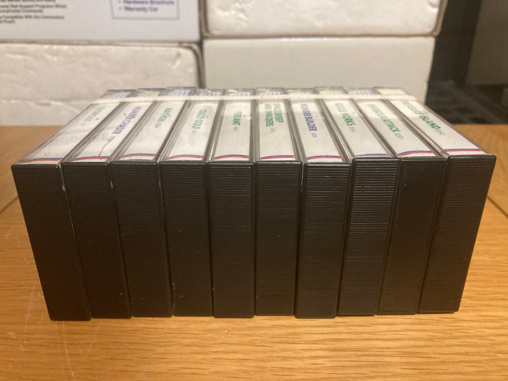
Returning to my comprehensive school in January 1986 revealed a few other class mates were also lucky enough to receive this great system for Christmas and many after school Icicle Works sessions did ensue (for a couple of months at least).
LikeLiked by 1 person